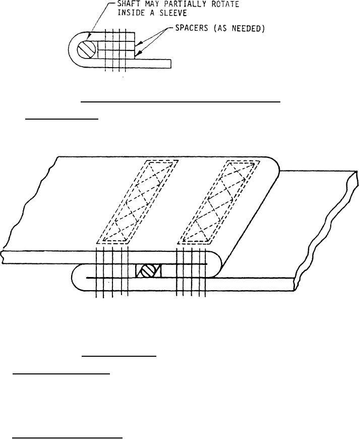
FIGURE 2.
Assembly of webbinq to a metallic component
*
3.14.6 Webbinq assembly.
The webbing assembly shown in Figure 3 is designed
to permit the force to the steel bar to be in either direction along the centerline
of the webbing. The fold of the webbing will act as a buffer and under normal
conditions this buffer will be in compression.
NOTES :
1.
Force may be In either direction along the centerline of the webbing.
2.
Only straight stitch shown.
The recommended double "W" configuration is shown.
3.
FIGURE 3.
Webbing assembly
3.15 Cable or strap clamps. Cables or strap clamps may be used for attaching
the cable or strap to the hoisttng attachment or the lifting attachment. A uniform
pressure shall be maintained on the cable or strap throughout the length of the
clamp. The loop shall be provided with an extra heavy cable thimble. The loop
formed by the clamp shall have at least the same failure strength as the cable or
strap.
3 . 1 6 Cable or strap terminals. The failure strength of swaged-type terminals
using cable or strap assemblies shall be not less than the minimum allowable
breaking strength for the type and size cable or strap to which the terminal is
attached.
9
For Parts Inquires submit RFQ to Parts Hangar, Inc.
© Copyright 2015 Integrated Publishing, Inc.
A Service Disabled Veteran Owned Small Business